What to buy
If you're considering building one of these, there are some must-haves and some optional extras. How you put it in a case I'll leave up to you.
Minimum shopping list
A Raspberry Pi.
FlightTracker has been tested on:
- RPi 3B
- RPi 4B
- RPi Zero 2
- RPi Zero W
- RPi 5
- If your device isn't on this list and you're feeling brave, give it a shot and let me know if FlightTracker works.
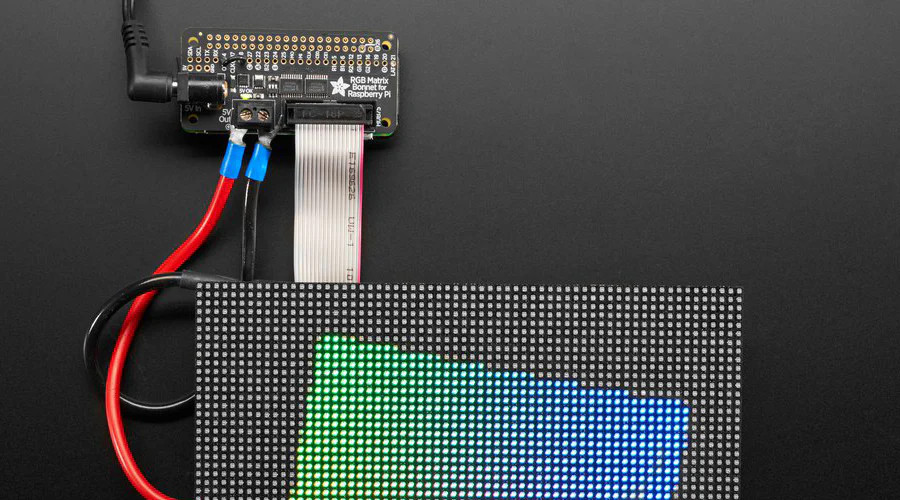
And the following bits for the display:
- RGB LED Matrix Panel - 32x64 - 1:16 Scan Rate
- Adafruit RGB Matrix Bonnet for Raspberry Pi
- Power supply (5V 8A)
There are cheaper alternatives to be found on the likes of AliExpress for most of the above, but if you want something to work first time I recommend going to a reputable retailer. In the UK I try and use Pimoroni where possible. If you do insist on buying from elsewhere make certain it's a 1:16 scan rate screen your buying; it should have 16S printed on its somewhere, avoid panels that say 32S.
Plug everything together and you'll be ready to get the code running.
Do not plug a USB power supply into your Pi at the same time as the RGB Matrix Bonnet's power supply. This can fry your Raspberry Pi. You only need the power connection that goes to the bonnet - it will supply power to the Pi as well.
Getting the best performance from the screen
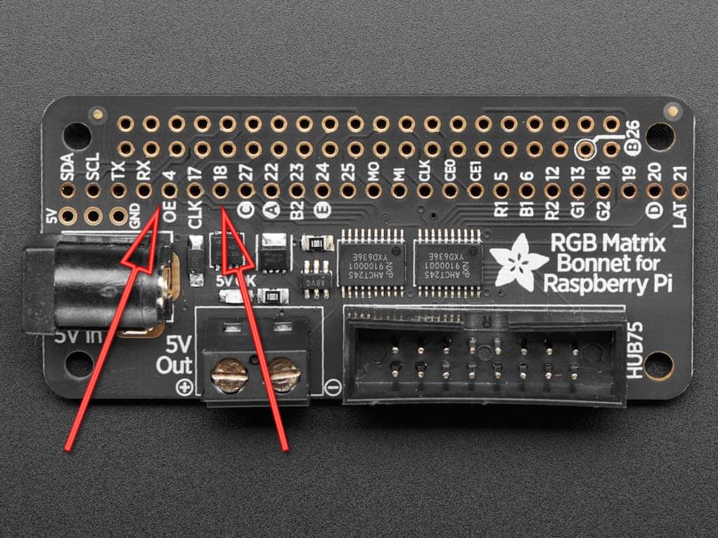
If you're running the code on a Raspberry Pi 5 you can ignore this. For everyone else I recommend soldering a small bridge between the 4 (OE) and 18 pin on the bonnet, as per the guide. It increases the quality by using the sound card to perform some
of the data signalling, however this also means you can no longer use your sound card whilst the bonnet is plugged in.
When installing the software you will be asked whether you soldered this connection.
3D Printed Case
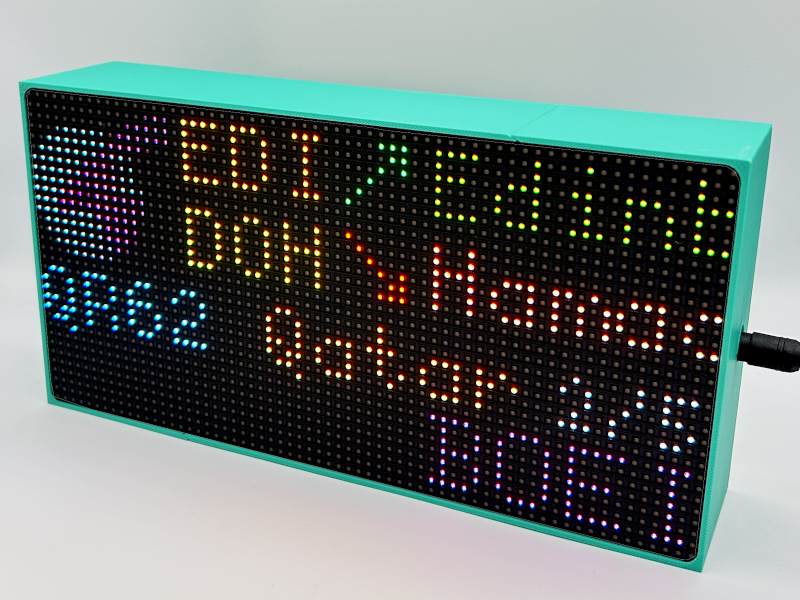
There's an official 3D-printable case for FlightTracker, designed for the 64×32 HUB75 RGB LED matrix (4mm pitch) from the shopping list above.
- Works with any Raspberry Pi model — full-size boards (Pi 3, 4, 5) and smaller boards (Pi Zero W, Zero 2)
- Two-piece interlocking design, prints on a normal-sized print bed
- Built-in tabs hold the matrix securely — no extra fixings needed
- OpenSCAD source available, so it's fully customisable
- Licensed CC BY-NC 4.0 (non-commercial)
Download the ready-to-print files or grab the OpenSCAD source:
Optional extras
Everything after this point is not needed if you just want to build your own FlightTracker.
A couple of people I know bought all the parts above, then got stuck because they wanted to make the "perfect" version of it.
What follows is how I built mine. Don't treat it as a blueprint; it's just here for inspiration.
Toggle switch and power LED
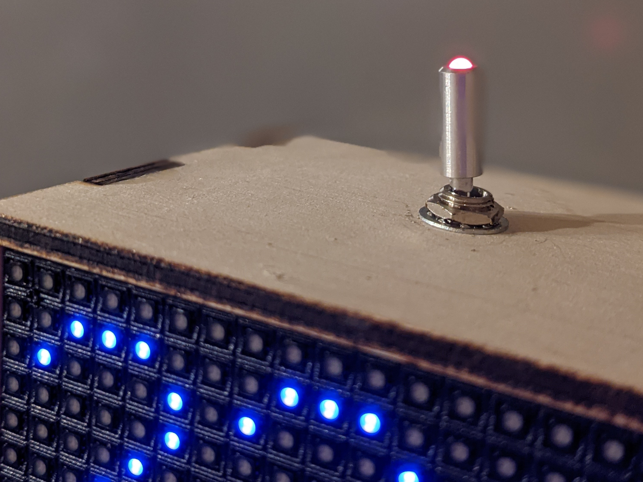
When you put the device in a case it's nice to have a power switch on the side to toggle the device on and off. I use the following switch, which has a built-in LED to show when the device is powered.
Simple wiring
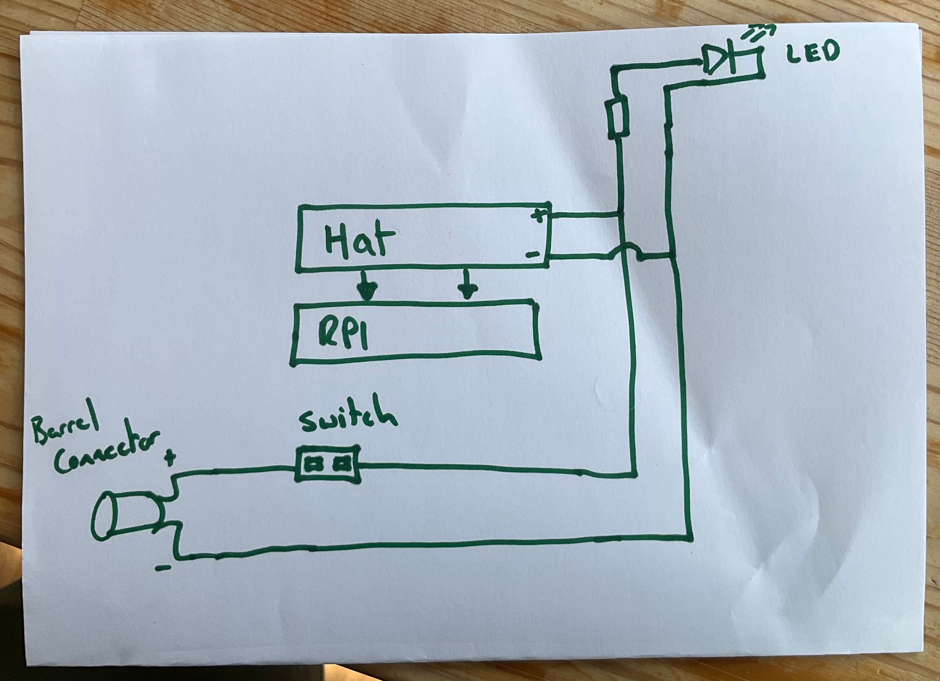
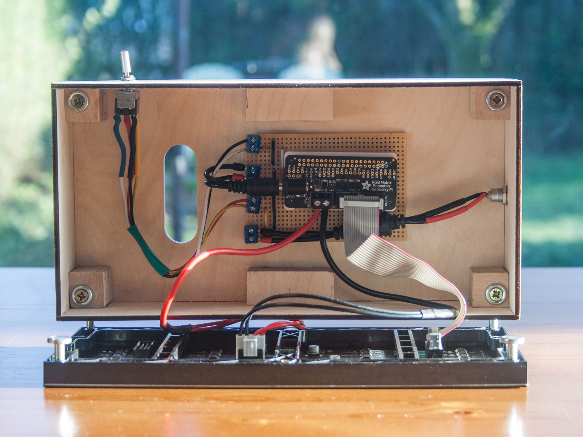
The simple version is to wire power via the switch and hook the 5V directly to the LED. This is how it was originally wired in these pictures. You'll need to put a current limiting resistor between the LED and the 5V line. I think I went with around 330R.
Blinky LED
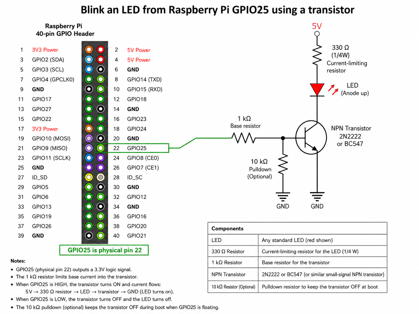
If you want that LED to blink when the device is searching for flights I recommend driving the LED indirectly via a transistor to avoid asking too much of the GPIO output.
25 of the Pi to the LED driver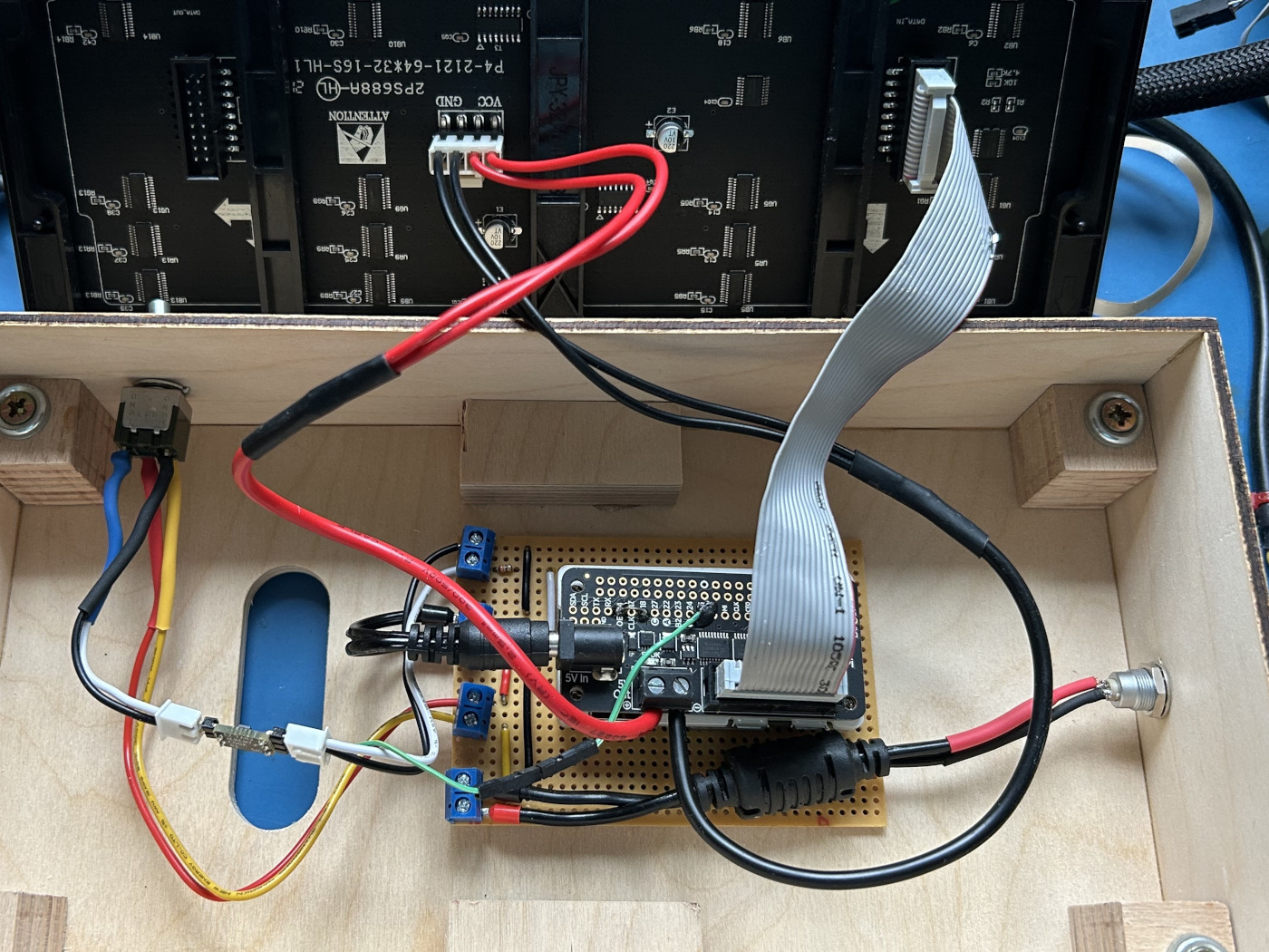
I used the same 330R resistor with an EZ Fan2 Tiny Raspberry Pi Fan Controller by Jeremy Cook. That gives you something like the following circuit to light up the LED.
Looking for a way to contribute? I'd love some better instructions and illustrations of the various ways to wire up a FlightTracker box.
Detailed circuits and illustrations
There aren't any. At the moment anything beyond the basic wiring is up to the person putting this together. Honestly, I find it difficult to know the amount of detail someone needs to wire something up if this is their first foray into a little bit of wiring. Do I need to explain how to use prototyping board?
I could maybe have my arm twisted to release a dev board with everything pre-wired and you just plug in a Pi and a screen.
If you've got strong feelings about this then raise an issue at GitHub and we can figure out what the minimum viable level of documentation here should be.
